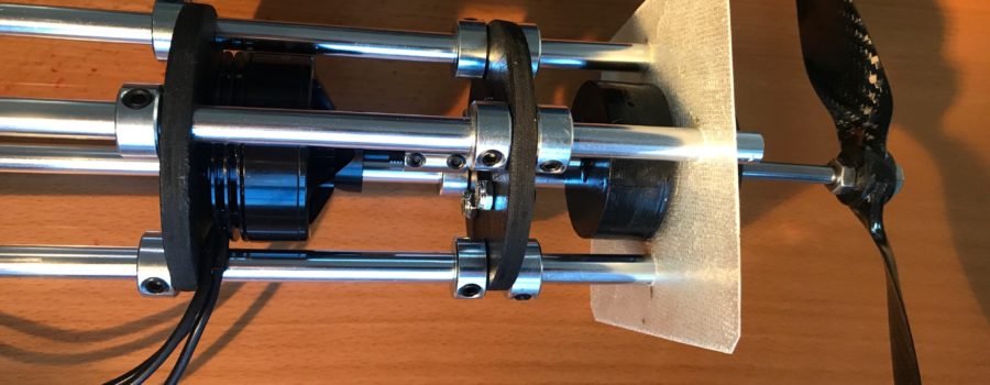
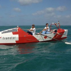
As we proceed with building various aspects of the autonomous boat, we will share the details here. This week, we are moving forward with the electric drive system, which is detailed here. You can also watch the video below to hear Colin describe our prototype pod motor.
There are two primary ways of driving a boat propeller using an electric motor.
Pod Motor
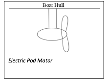 This method involves having the motor (and reduction gear if used) encapsulated in a waterproof pod which is fully immersed in the water. A waterproof seal around the drive shaft prevents water from leaking into the pod at this location. This is how typical electric trolling motors are configured.
The structure supporting the pod can be foil shaped to minimize drag, and the wiring is run through this structure.
Through-Hull Propeller System
 This system involves having the motor (and reduction gear if used) situated inside the hull. The drive shaft runs through the hull (with a seal at this location), and an outer support stabilizes the shaft.
A Comparison of the Systems
The electric pod motor has the advantage of less hydrodynamic resistance. With the through-hull setup, it is difficult to create a fairing around the exposed prop shaft, so this is an area vulnerable to turbulence. Additionally, the section of shaft spinning in water is exposed greater friction than when spinning in air, adding further friction to the system. On the other hand, it is easier to shape all components of the pod system to reduce turbulence.
Additionally, for maximum performance the propeller should be aligned so the thrust is parallel to the vessel. Unlike the pod system, the through-hull shaft must be angled, further reducing efficiency. It is possible to use a flexible shaft, however, this presents additional challenges, such as the potential for metal fatigue and shaft seal issues.
Another benefit of the pod system is the motor is fully protected (unless the shaft seal fails) from water immersion. With the through-hull system, the motor is more vulnerable. If a small bit of water enters the main hull (which is more likely than the pod seal failing) the motor is very vulnerable. It could be protected with a waterproof casing; however, this would require a second shaft seal adding an additional 4-5 watts of parasitic drag.
Summary
Overall, we feel that the pod drive system is superior to the through-hull drive. It is more efficient, and provides greater motor protection. Typical off-the-shelf trolling outboard motor systems cannot be used as they are extraordinarily inefficient (about 20% overall efficiency), using brushed motors, poorly shaped propellers, and non-hydrodynamically shaped components. There is a huge amount of room for improvement as one German company has shown. Torqeedo, a high performance electric outboard company, makes pod-style trolling motors with brushless motors, streamlined components and relatively efficient propellers. Their motor/propeller systems have an overall efficiency rating of 50%, which is 250% better than the industry standard.
Torqeedo motors could potentially be used, however, they are still not ideal. The motor controller is programmed to work only with their integrated intelligent battery system, so this would need to be modified. Additionally, the drive shaft seal is only rated to 300 hours (about 12 days running continuously). This is likely a conservative estimate, and with the motor running at less than 25 percent capacity, it is likely that the seal would last for more than double this time, however, it is a risk.
Overall, the best solution is creating a custom motor pod. It should be possible to create an even more efficient motor than Torqeedo. There are several aspects of the Torqueedo motor that reduce efficiency due to design parameter relating to typical customer applications (such as requiring a more robust, and not-ideally-shaped propeller), that could be improved upon. Hydrodynamic shaping of the overall system could be significantly improved, and installing a magnetic coupler would be another means of reducing parasitic losses.
Overall Motor Pod Design
Motor
 The motor will be a brushless design due to the greater efficiency (about 20 percent more efficient than brushed) and reliability. Typically, brushless motors spin faster than brushed motors, and many have their greatest efficiency at several thousand rpm. This is too fast for ideal propeller function. The propeller shouldn’t be spinning faster than 1000 to 1200 rpm for decent efficiency (300 or 400 rpm with high torque is even better, however, the propeller size becomes prohibitively big, creating other problems). One way to bring the rpm down is to use a reduction gearing system, however, this does add additional resistance, and is another potential fail point. We will be experimenting with brushless motors with low KV ratings (rpm per volt), and will determine if a direct drive system will be satisfactory.
Pod case
The motor, motor controller, drive system, and one half of the magnetic coupler will be assembled within a supporting framework, and then inserted and affixed into a tube. One end of the tube will be sealed with a thin barrier, which will separate the two halves of the magnetic coupler. Thrust bearings are required at each magnetic coupler, to resist the magnetic attraction. The immersed bearings will require ceramic balls, which fair better in an immersed saltwater environment than stainless. One axial bearing (and support) will be required between the magnetic coupler and propeller. The wiring for the motor will emerge through a hole, which will be sealed with epoxy. After the motor and drive system has been secured, the other end of the tube will be sealed making it fully watertight. The tube will then be inserted into a faired housing
Magnetic Coupler
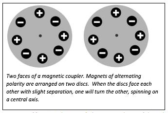 One other element we plan to incorporate into the motor system is to use a magnetic coupler, instead of a shaft seal. A magnetic coupler is a mechanism that conveys torque through an impervious barrier by using a series of magnets that face each other. When one half of the coupling spins, the magnetic attraction spins the other half. The magnetic coupler provides three advantages over a standard shaft seal: there is virtually no resistance (shaft seals usually create 4-5 watts of friction in the system), there is zero chance of the pod leaking since it can be 100% sealed, and the system will last indefinitely (unlike shaft seals, which eventually start leaking). The main disadvantage of a magnetic coupler is it will start to slip in higher-torque applications; however, it will work well with our low-torque drive system.
One Motor Pod Vs Two?
We are still deciding whether to use two inline propeller pods or one single one. From an efficiency standpoint, there is no advantage to using two. The advantage of using two prop systems is redundancy. If one fails, the other will be able to keep the boat moving.
Overall, the decision will rely on a risk analysis of the systems – how vulnerable are the pod systems, and is there a medium-high chance of failure? This can be determined through field and tank testing. We will tank test trial pods continuously for a month, and extensively field test. The two greatest dangers are mechanical malfunction and prop fouling.
Running two propellers instead of one is the equivalent of four-wheel drive in a car as opposed to two. The propellers still turn at roughly (fractionally slower, because slippage of each prop is reduced) the same speed (as a single prop system), but the torque required to turn each prop is reduced. One slight advantage of a two-prop system is smaller propellers can be used to greater efficiency, since they (individually) are not pushing the water as hard. The main disadvantage is the extra drag created by the appendages of the second prop unit, and a more disturbed water flow for the aft propeller unit).
Propeller(s)
 The type of propeller used is an extremely important part of the overall efficiency. Generally, the most effective propeller designs commercially available are for RC airplanes, rather than boats (prop efficiency is more important in airplanes than typical small boat applications). Since the aerodynamic aspects the props are designed for is basically the same as fluid dynamics, these propellers work very well in an aquatic setting. The two main aspects of a propeller relating to application are diameter and pitch. The diameter is a measure of the diameter of the circle made by the tips of the blades when spinning. For a two-blade propeller, this is simply a measurement from tip to tip. The other important measurement is the pitch. Pitch is the measurement of how far forward the propeller will move with each revolution (assuming no slip – imagine a screw going into piece of wood). Pitch is determined by the angle of attack – the greater the angle of attack the more the propeller will move forward with each revolution. In reality, depending on a range of variables, the propeller will not move through the water at the rate of pitch. We’re assuming that the prop will have about 20% slip, meaning a propeller rated with a 5” pitch, will only actually move forward about 4”. This number will continue to be variable in the field, with headwinds, tailwinds, etc all having impact.
Propellers are rated using two numbers – the first number is the diameter of the spinning circle in inches, and the second indicates the pitch (forward movement with each revolution) in inches. We will be experimenting with various sizes, and field testing to see which gives the greatest speed/watt. One potentially suitable propeller (after conversing with Rick Willoughby, an engineer with a specialty in high efficiency low-powered propellers) is a three bladed rc prop with a 10×7 rating. The “7” rating means it will move forward at 5.7 knots (or about 10 km/hr) (with no slippage) at 1000 rpm.
Electrical Supply
A voltage converter with 95% efficiency will convert the voltage down from the 12 volt storage supply to a suitable 4 or 5 volts for the motors.
Motor Control System
It will be important to control the speed of the motors to make maximum use of the available power. For a displacement boat making way through the water, the required propulsive power increases in proportion to the cube of the speed. This means if you want to double your speed, you need eight times the power. In other words, with a limited power supply if you used all available power over one hour, or rationed the power over eight hours, you would go four times further by travelling slower for eight hours. This means much greater efficiency will be achieved if the motors are running continuously at varying rpm, rather than running sporadically at higher speed. A microprocessor can be programmed react to various sensors including battery voltage, solar intensity, time of day, etc to decrease or increase rpm when necessary. At the very least, motors can be programmed to run at 80 watts at night, and 120 watts during the day.

